Building a Eurorack enclosure with IKEA RAST and OpenBeam

After writing my article about the things I wish I’d known before building my original enclosure, I deciced to go ahead and undertake the massive project of converting all I had so far to eurorack proportions.
Since my project’s specs don’t entirely match Eurorack specification (my power is +/- 5V for instance), I’m only aiming to cover the mounting and dimensions in this article.
How much room will this get me?
In height: 12 U or 4 rows of modules.
In width: 115 HP.
Where 1U = 1.75 inches or 44.45mm and 1HP = 1⁄5 inch or 5.08mm.
Materials
The main ingredients for my enclosure are as follows:
- 1x IKEA RAST Chest of 3 drawers (UK IKEA link, but should be available worldwide, check you local IKEA)
- 8x 600mm OpenBeam - from this link you’ll want to buy 3 sets of 3. Alternatively buy in increments of 1 from Makertronics
- 16x 40x15mm Right angle bracket- I got some off ebay
- A bunch of M3 machine screws - mine are about 12mm long. It wouldn’t hurt to get a few hundred of them for mounting modules later too.
- M3 hex or square nuts. Square ones work a bit better for this but are generally harder to find and more expensive. Get about 400 or so of them, you’ll be filling up rails with them.
Tools
A few tools will be needed to build this enclosure:
- A long ruler (one of about a meter will be helpful)
- A small ruler for the smaller measurements
- Pencil
- Power drill
- 2.5mm drill bit
- Screwdriver (to match the M3 screws you got)
- Hacksaw
- Vise or something else to clamp openbeam, I used a portable folding workbench (known as Workmate)
- Optionally a metal file to smoothen the cut
Build
First and foremost, make sure all the parts of the IKEA RAST are present. Don’t assemble it yet. Look through the build instructions, and identify which parts relate to the drawers. Keep those apart, you won’t need them for the enclosure, but they make for good spare wood. You may want to keep at least one spare drawer front.
Identify the left and right wooden panels, and figure out which sides of these panels will be at the front of the enclosure. It might help to mark them with a pencil.
Decide how much room you want to leave at the front of your modules. I personallly like having it in a way that no module hardware ssticks out beyond the sides of the cabinet; that way I can lay it down on its front without worrying about damaging something, should I need to. For me, this ended up being about 30mm from the rail to the edge of the side panel.
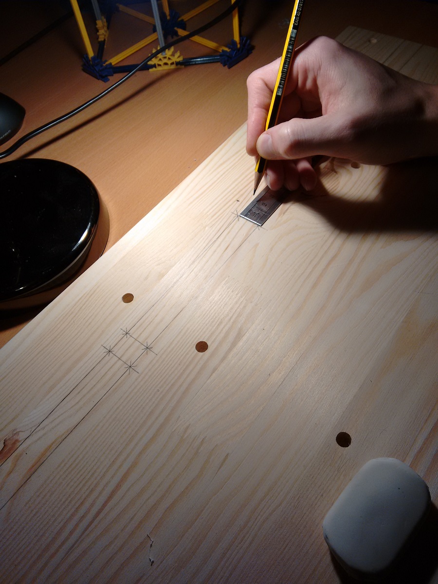
Draw line(s) parallel to the height of the panel
You’ll want to draw a line at the following distance from the front of the side panel: panel front clearance + panel thickness + rail thickness + angle bracket hole offset.
In my case, my panel front clearance is 30mm as mentioned earlier. My panels will all be 3mm thick acrylic. OpenBeam is 15mm thick. The angle brackets I used have a hole offset (from outer edge of the corner to centre of nearest hole) of 15mm. 30 + 3 + 15 + 15 = 66mm from the side. Measure this distance at the top and bottom with your small ruler and make a small mark, then use the large ruler to connect the two in a long line. Do this on the left and right side panels.
My angle brackets have two holes to a side, so I measured the distance between their centers, and drew another line at that distance from the first one.
Mark the position of the top panel on the side panels
Locate the top panel of the cabinet and join it to the left panel (follow IKEA instructions) - don’t screw them together yet however.
Draw a line on the side panel, on the underside of this top panel, perpendicular to the line(s) you’ve already draw; make them cross.
Repeat this on the right panel, then detach the top panel again.
Mark drill points on the vertical lines
From the perpendicular line you’ve just drawn, measure 7.5mm down and mark that intersection on the vertical line(s). This is where you’ll drill for the very top OpenBeam mounting later.
From that point down, measure 120.65mm (4 3⁄4”), and make another mark. This is the vertical distance between mounting holes for a 3U tall module. This is where you’ll mount the next angle bracket.
From this point down, measure 16mm. This is 2 x 7.5mm of two halves of an OpenBeam rail, plus a millimeter of leeway. Mark again. Here begins row two.
From there, measure 120.65mm (4 3⁄4”) down again and make another mark. You get the idea. Do this until you’ve covered 4x 3U, at which point there is more room as you’ll find if you attach the bottom plank to a side panel.
Now, to help drilling, use a wood sharp wood screw to press some preliminary dents exactly where you’ve marked the drill points. This will help stop your drill bit from wavering and drilling inaccurately.
Drill the screw holes
Use a 2.5mm drill bit for this (no bigger). Drill all the holes you marked and dented, to a depth of around 10mm or less; you don’t want to drill all the way through. I found that wrapping a bit of electrical tape around the drill bit helped limit the depth to which I drilled.
Attach the angle brackets
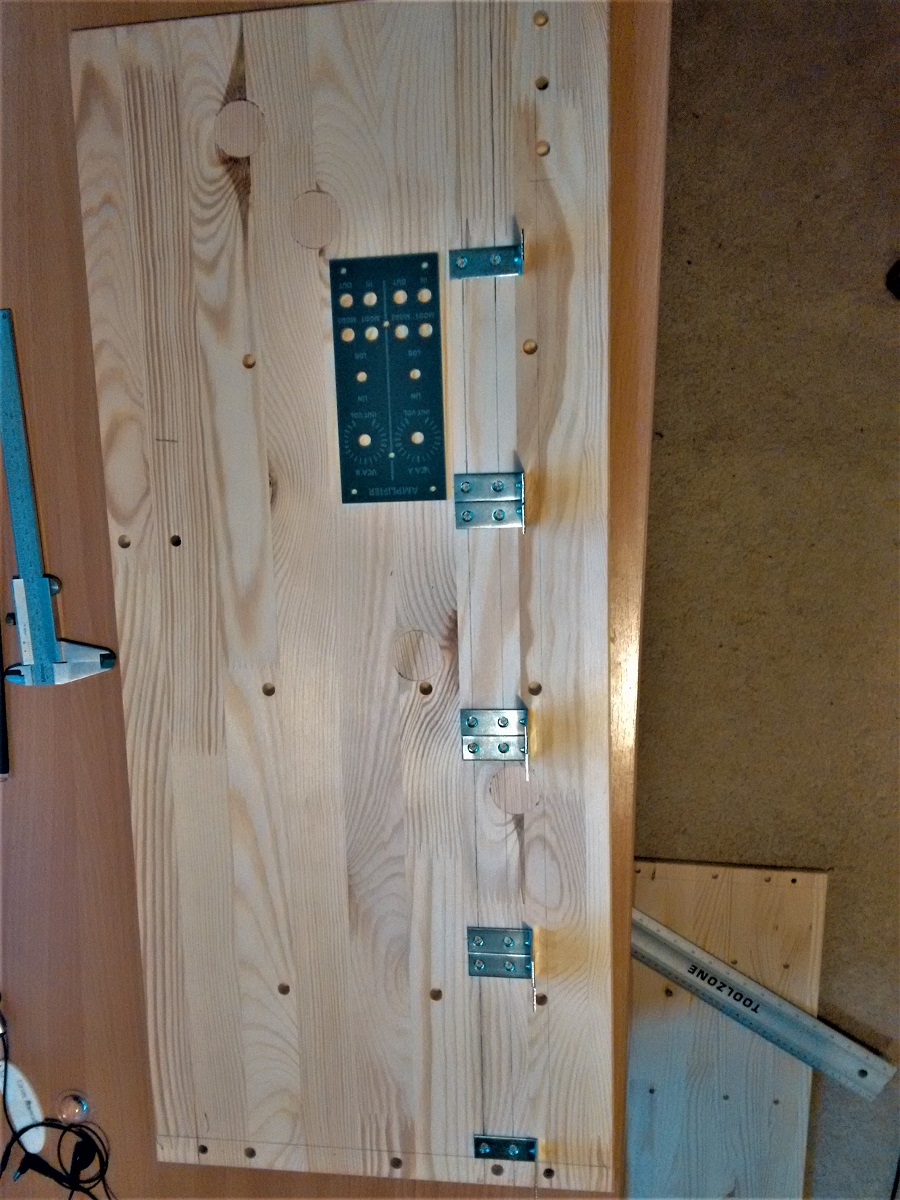
With the corner facing forward, mount all the angle brackets to the side panels. Use either your M3 machine screws, or self-tapping wood screws that are short enough. I didn’t have any of those on hand so I use my M3 screws, which worked out absolutely fine.
Assemble the enclosure
Now that the angle brackets are installed where they need to be, you can put the enclosure together. Follow IKEA’s instructions, while leaving out the drawers.
Prepare the OpenBeam rails
Trimming
The inner width of the enclosure is just 587mm wide, which is slightly less than the 600mm the OpenBean rails come in. Mark 13mm from the edge of each rail, and saw that bit off with a hacksaw. You cand then use a metal file to smoothen the edge a bit, if you like.
Add nuts
In each rail, insert about 40 nuts (should be plenty) in what will be the front-facing side. To help avoid them falling out while you’re working, you can put a screw in one of these nuts neat the end, and do the same on the other end when it’s filled up.
On what will be the rear side of the rail, insert 4 nuts, or 2 if you got angle brackets with just 1 hole to a side.
Do this for each of the rails.
Mount the rails in the enclosure
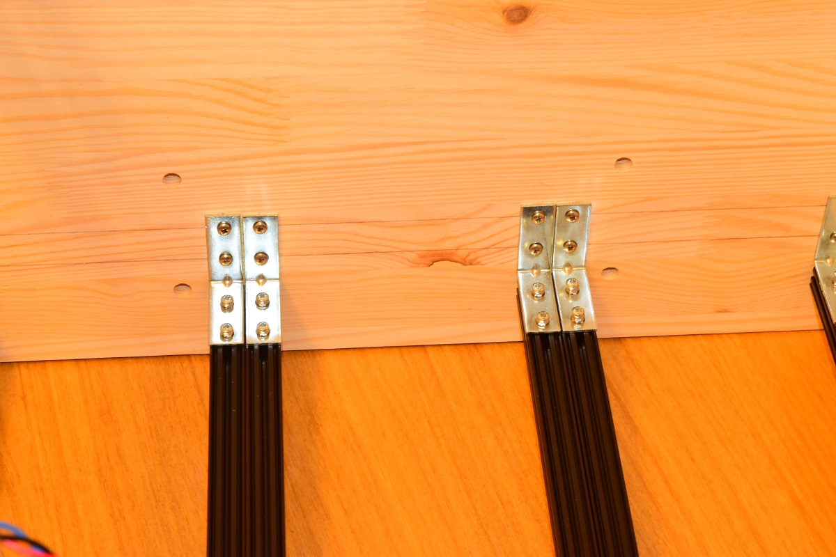
Position a rail in front of a pair of angle brackets, and use a small screwdrive or some other pin to move the nuts in the back of the rail to match the holes in your angle brackets. Then insert screws through the angle brackets and into the nuts still in the rail. Tighten the screw so it goes the rail is fixed in place. If your screw is too long to produce a tight fit agains the angle bracket, you can add a nut or two on the screw before sticking it through the angle bracket.
Repeat this for all the holes in your angle brackets, with all the rails.
Now, you can remove any screws you put in to keep the nuts in the rail, as they’ll be held in by the sides of the enclosure.
You’re done!
That should be pretty much it, for module mounting rails at least.
Power
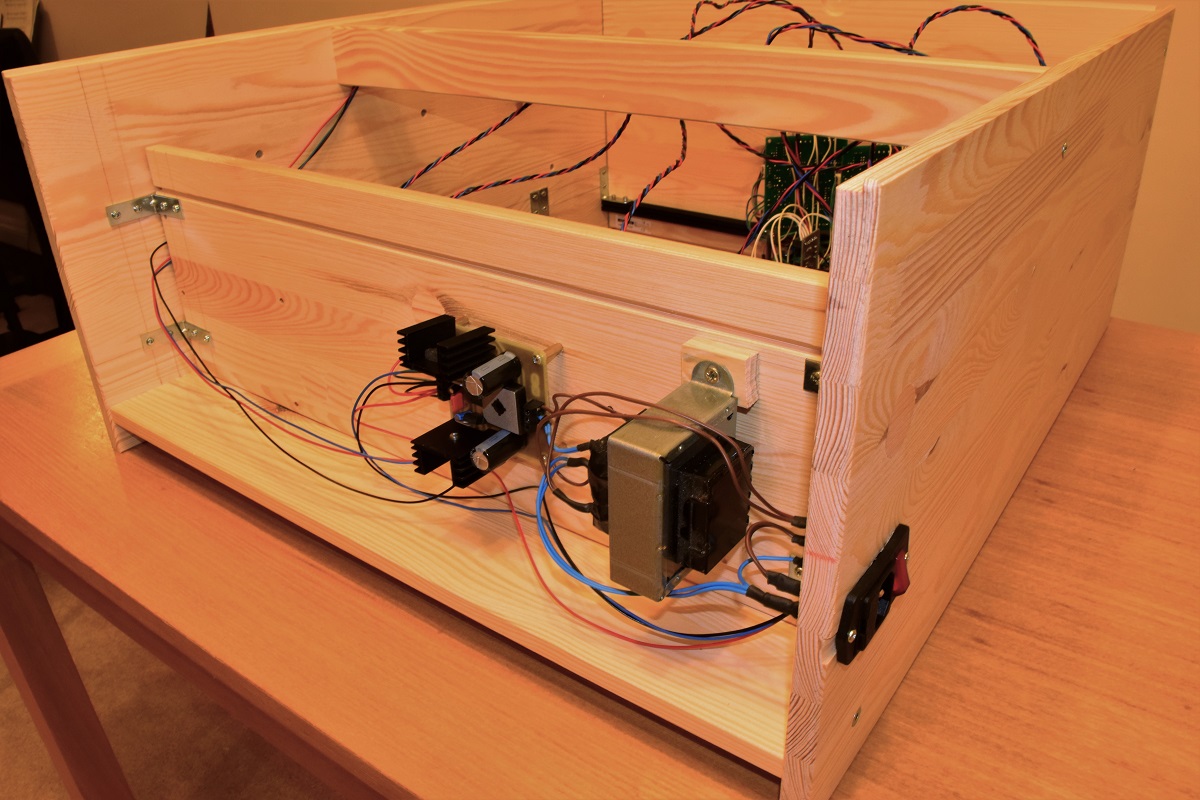
My power supply is one I produced myself, consisting of an IEC connector with lit up switch, transformer, and a PCB with regulators.
I used a drawer front panel and some more angle brackets to close off the bottom end of the enclosure, installing it level with the top of the plank in the front of the bottom.
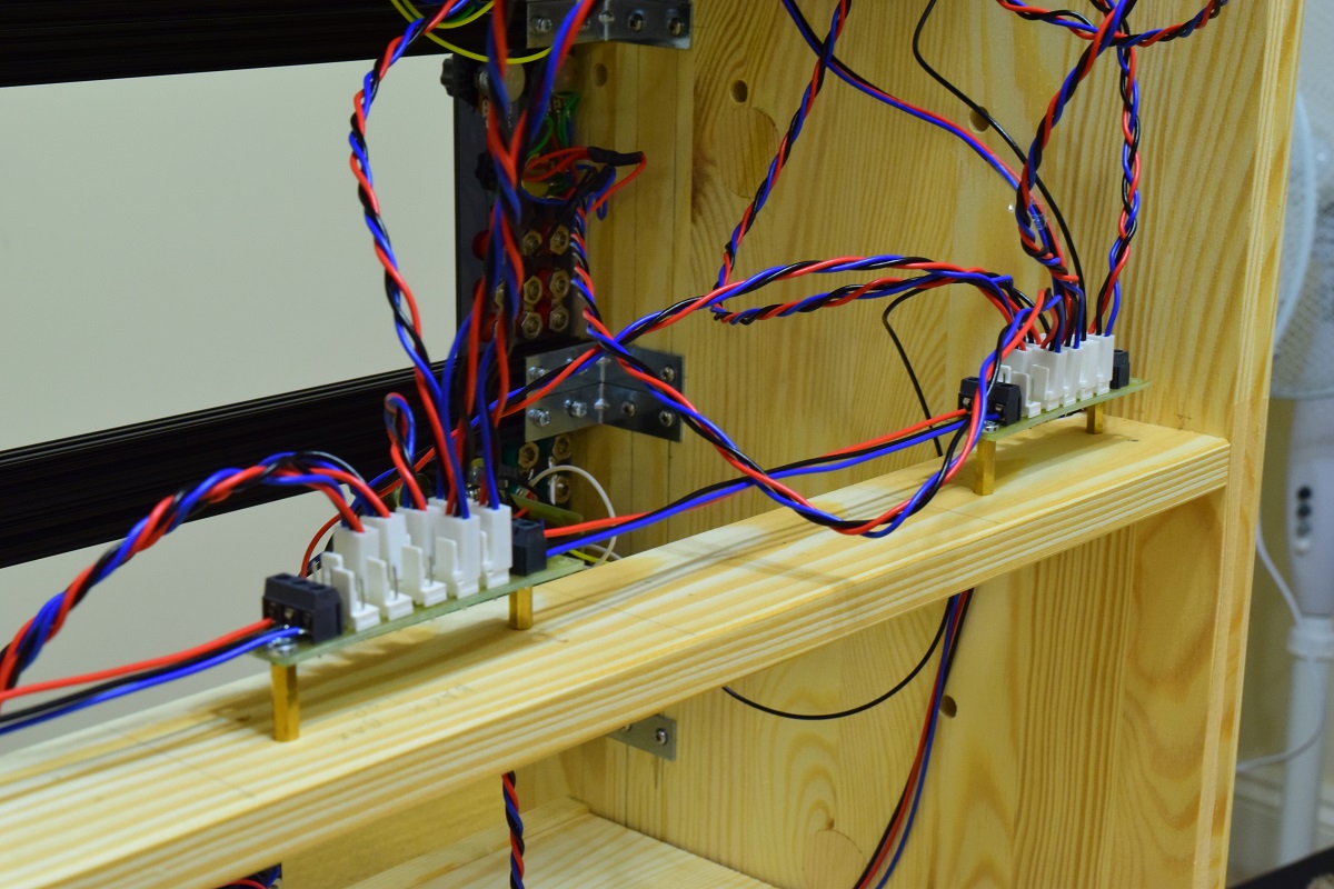
I then used a large drill and a file to make the hole for my IEC connector on the side of the enclosure.I mounted the transformer upside down onto the plank I’d just installed, with some screws. Then, I predrilled and installed PCB standoffs in the wood to mount the PCB. From there, I run wires up to the rest of the cabinet, where they are attached to some simple PCBs that provide 10 3-pin molex connectors each. These connector PCBs in turn are mounted on the narrow plank at the back of the enclosure, which is perfectly positioning for this kind of thing. This way, my modules plug in there with a single connector each.
This part is notably not very Eurorack, but I figured I’d include it for completeness’ sake.
Later, I’ll write an article on making front panels, including some dimension helpers for design.